This Article in its original form fist appeared on LinkedIn.com on 1/31/2018. A slightly Modified article is below.
—————————————————————————————————————————————-
This article is intended and directed to educate the end user. If you are on sales, keep on reading, just don’t get offended with my opinions as expressed here.
What I mean with this title is that there is no hiding the real vacuum pump facts in a performance curve. I have been mulling over on how to approach these many currently fashionable claims of “Energy Savings” , “My pump is better than Yours”, “This pump is the best thing since sliced bread” from these companies that claim expertise and require blind faith when all they offer is a pump in a box (or a cabinet, which is the latest trend). I just wonder….Why are you hiding your pump? is it ugly? or just a pump clone that you are working to the limits of its design?… but I digress, back to performance curves.
I cringe every time I hear these sales arguments that are never backed up with any form of data. I tried my best to find a “typical” performance curve to highlight the various items that the user have to politely ask from their vendors. Yes, You can be polite and firm at the same time. There should be no secrets between the end user and their pump supplier. Once you have the curve on hand you have to make a copy of it and start marking it up with your own actual performance requirements.
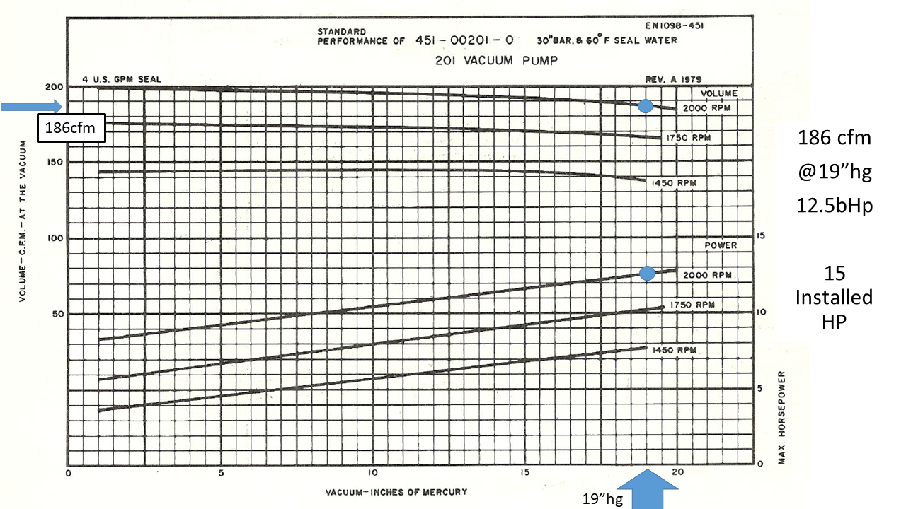
I have included below a curve that is no longer used and have also deleted most of the identifying marks to keep the pump anonymous, so we can have a technical discussion without throwing anyone under the bus. Image copy is below.
E-mail me for an Unmarked copy of the curve.
First, you have to find out in the curve you requested, your own “setpoint”. This is your required flow AT the desired pressure for YOUR specific application. In my case, I have chosen a generic “Setpoint” of 185cfm@19″hg, and have marked my copy accordingly.
Let me take a moment to explain what this “Setpoint” is NOT.
- It is NOT the maximum flow achievable- for this pump that would be about 199 cfm (look at the left of the curve)
- It is NOT the maximum possible pressure attainable by the pump- for this specific pump, the factory maximum allowable working vacuum level is 20″Hg. Look at the end of the top curve, the one of 2,000 RPM. (I’d have to address why it’s only 20″hg, cavitation on liquid ring pumps, difference between 1 and 2 stage pumps on a different post)
This “setpoint” is the working flow at the desired pressure, that the customer has determined by any standard method, or process requirement, that he deems necessary for his process to work properly.
The next item to look at is the horsepower. Every pump has a power requirement to compress the air/gas to get it from ambient, to any given pressure/vacuum. Each piece of equipment has its own power requirements that have to do with the technology being used and the specific “setpoint”. It behooves you, the customer to make sure that the equipment is NOT being used outside the working parameters of your equipment design criteria and to make sure the electric motor is not being worked to the limits of its own “SF”(Service Factor). Electric motors working on the service factor is another whole conversation beyond the scope of this article.
Buyer beware, if your vacuum pump has an “automatic inlet valve”, (aka.”Unloader valve”, “Limiter valve”, etc) it means that the manufacturer is patently aware that the pump has limits into the capability of the pump to actually deliver the maximum flow at a moments notice. Those automatic valves on any vacuum pump inlet will strangle/choke the pump to keep the pump from being “inundated” with in-rush of ambient air. These valves restrict the air flow with a partial closure and do extend the actual pump down time on the system. They are also used when the high vacuum level is reached to isolate the pump and let the pump run “Unloaded” which is nothing more than “dead heading” the pump (running the pump with no flow), just to clean the internal filters and cool off the pump. If you see a pump that has a cabinet with a control panel that will monitor it constantly, brings it online and has a specific sequence for start up and shutdown, look deeper and it’s possible you will find one of these “Unloader” valves. A Mechanical gimmick is no substitute for an experienced Vacuum designer.
This is a conundrum for the manufacturers, do they allow all that air to enter the pump- which will then require a bigger motor- , but then the discharge filters may become saturated and spit oil thru the discharge? or do they put these valves and control them automatically from the pump control panel, and just obviate how they affect pump performance? The end user usually ends up with a pump that will work restricted most of the time to protect itself. What good is a pump if you can’t use it to its full potential? Then of course, they will be happy to sell you the next size up.
This is where the rubber meets the road and the sales pitch starts to deviate into unknown territory. The salesman starts sweating and will tell you…”Let’s call the factory to get an answer for that, they have an expert there”.
The facts don’t change, just look for them. At this point I usually just ask the customer… do you have the performance curve? I’ll give you my honest evaluation of whatever equipment you are considering , just get me the curve and lets discuss your process requirements. The curve is just the beginning of a straight conversation.
If you have any questions, please don’t hesitate to write me a note. I tried to keep this concise but there are volumes written on this subject and each application and customer need is a bit different than the rest.
Next Article Idea: Control valves Vs. VFD controls, Can they actually save money?. Let me know your thoughts on this subject and I’ll try to incorporate them and give you credit.
Stay Tuned.
Regards, Angel Diaz